A gear is a rotating circular machine part having cut teeth that mesh with another part to transmit torque geared devices can change the speed torque and direction of the power source gears are used to transfer motion and torque between machine components in mechanical devices.
Gears of different sizes change torque, creating a mechanical advantage through their gear ratio. It is necessary to accurately understand the differences among gear types to accomplish the necessary force transmission in mechanical design.
Different Types of gears
There are all types of gear that are used in various machine parts and industries.
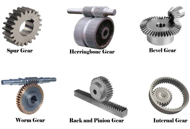
Spur gears:
A spur gear is the simplest type of gear they consist of a cylinder or disc with teeth projecting radially though the teeth are not straight-sided. The edge of each tooth is straight or aligned parallel to the axis of rotation. These gears mesh together correctly only if fitted to parallel shafts.
Spur gears are excellent at moderate speeds but tend to be noisy at high speeds. This is different from helical gears with more than one tooth in contact and transmits torque more smoothly.
Helical gears:
Helical gears are used with parallel shafts similar to spur gears and are cylindrical gears with winding tooth lines. They have better teeth meshing than spur gears and have superior quietness and can transmit higher loads making them suitable for high-speed applications. Helical gears come up with right-hand and left-hand twists requiring opposite hand gears for meshing pairs.
Double helical gears:
Double helical gears are a variation of helical gears in which two helical faces are placed next to each other with a gap separating them. Each face is identical but has opposite helix angles. Employing a double helical set of gears eliminates thrust loads and provides smoother operation.
Double helical gears are commonly used in enclosed gear drives.
Herringbone gears:
Herring bine gears are very similar to the double helical gear but they do not have the gap separating the two helical faces. Herringbone gears are typically smaller than the comparable double helical gear and are ideally suited for high shock and vibration applications.
Herringbone gearing is not used very often due to its manufacturing difficulties and high cost.
Bevel gears:
Bevel gears have a cone-shaped appearance and are used to transmit force between the two shafts which intersect at one point. A bevel gear has a cone as its pitch surface and its teeth are cut along the cone.
One of the common uses for the bevel gears is for changing the power transmission axis this makes the operation smooth and quiet.
Spiral bevel gears:
Spiral bevel gears are beveled gears with curved tooth lines. Due to the higher tooth contact ratio. They are superior to straight bevel gears in efficiency, strength, vibration, and noise. They are more difficult to produce also because the teeth are curved and they cause the thrust forces in the axial direction.
Miter gears:
Miters gears are the bevel gears with a speed ratio of one. An engaging pair will always have the same number of teeth as the transmitting power between the intersecting axes.
Miter gears are used in machines to change the direction only. They do not cause a change in the shaft speed or torque.
There are straight miter or spiral miter gears.
- Straight miter gears offer the advantage of not having to deal with any axial thrust but they come with the limitations of straight bevel gears.
- Spiral miter gears produce axial thrust necessitating the need for thrust bearings.
Worm gears:
Worm gears transmit power through right angles on non-intersecting shafts. Worm gears produce thrust load and are good for high shock load applications but offer very low efficiency in comparison to the other gears due to this low efficiency. They are often used in lower horsepower applications.
A unique characteristic of this gear drive is that gear pair rotation can be locked. This is because the wormwood cannot turn the worm gear if it is set at a certain angle. However, worm gear can turn the worm it will at any angle. This property is utilized in applications that require self-locking mechanisms.
Worm gears come with certain disadvantages in that the transmission efficiency is not so good compared to other gears. Also, the fact that sliding occurs between the worm wheel during transmission makes lubrication a factor for smooth operation.
Hypoid gears:
Hypoid gear resembles a spiral bevel gear but some are marked differences. Unlike spiral gears, hypoid gear shafts do not intersect. These gears are placed offset to the crown wheel which is usually a spiral bevel gear. They achieve higher speed reduction due to their large contact ratio. The increased contact also permits higher load transmission while suppressing noise and vibration.
Gear racks:
It is possible to combine spur gears with a rack to convert rotational motion to linear motion. A rack consists of teeth cut in a straight row on a flat surface. These teeth have the same profile as the spur gear. The spur gear teeth types mate with the teeth on the rack similar to how they would mesh with another spur gear. When the gear rotates it pushes the rack in a straight line. The gear rack system is used in many products such as automobiles, stair lifts, and railways.
Crown gears:
Crown gears are a particular form of bevel gear whose teeth project at right angles to the plane of the wheel in their orientation. The teeth resemble the points on a crown. A crown gear can only mesh accurately with another bevel gear. Although crown gears are sometimes seen meshing with spur gears. Typical use is a crown gear and pinion system which allows a rotary motion to be shifted at 90 degrees.
Screw gears:
Screw gears are pairs of same hand helical gears with a twist angle of 45 degrees on non-parallel and non-intersecting shafts. The tooth contact is a point their load carrying capacity is low and they are not suitable for large power transmission.
Internal gears:
Internal gears have the teeth cut on the inside of cylinders or cones and are paired with external gears. The main use of internal gears is for planetary gear drives and gear-type shaft couplings. The rotational directions of the internal and external gears in the mesh are the same while they are opposite when two external gears are in the mesh.
Rack and pinion gearing:
A rack is a toothed bar or rod that can be thought of as a sector gear with an infinitely large radius of curvature torque that can be converted to linear force by meshing a rack with a round gear called a pinion. The pinion turns while the rack moves in a straight line such a mechanism is used in automobiles to convert the rotation of the steering wheel into left to right motion.
Epicyclic gear:
In epicyclic gearing, one or more of the gear axes moves. Examples of this different type of gear are sun and planet gearing. Sun and planet gearing is a method of converting reciprocating into a rotary motion that was used in steam engines.
Harmonic gear:
A harmonic gear or stain wave gear is a specialized gearing mechanism often used in industrial motion control robotics and aerospace. Its advantages over traditional gearing systems include a lack of backlash compactness and high gear ratios.
Cycloid gear:
The cycloid gear profile is a form of toothed gear used in mechanical clocks rather than the involute gear form used for most other gears. The gear tooth profile is based on the epicycloid and hypocycloid curves which are the curves generated by a circle rolling around the outside and inside of another circle respectively. This gear is a limitation because it works for a constant distance between the centers of two gears. This condition in most cases is impractical because of the involvement of vibration and hence in most of the cases, an involute profile of the gear is used.
Cage gear:
A cage gear also called a lantern gear or lantern pinion has cylindrical rods for teeth parallel to the axle and arranged in a circle around it much as the bars on a round bird cage or lantern. The assembly is held together by discs at each end into which the tooth rods and axle are set.
Caged gears are more efficient than solid pinions and dirt can fall through the rods rather than becoming trapped and increasing wear. They can be constructed with very simple tools as the teeth are not formed by cutting or milling. But rather than drilling holes and inserting rods, these gears are sometimes used in clocks. The cage gear should always be driven by a gear wheel but not used as the driver.
Magnetic gear:
All cogs of each gear component of magnetic gears act as a constant magnet with periodic alternation of opposite magnetic poles on mating surfaces. Gear components are mounted with a backlash capability similar to the other mechanical gearings although they cannot exert as much force as a traditional gear due to limits on magnetic field strength such gears work without touching and so are immune to wear. They have very low noise and no power losses from friction and can slip without damage making them very reliable. They can be used in configurations that are not possible for gears that must be physically touching and can operate with a non-metallic barrier completely separating the driving force from the load.
Read more blog like: Taper Turning – Methods and Process